
HomeGrown Solution: SimMan3G Chest Tube Adaptation
Title
Submitted By
HomeGrown Solution Number
Identification of the Problem
Unique Idea
Objectives
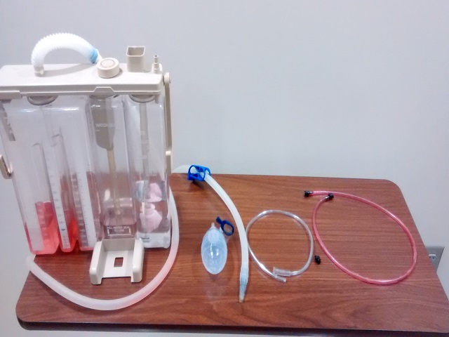
Supplies/Ingredients
- Chest drainage collection system
- 100cc Jackson-Pratt Drain
- 30" tubing with connectors from SimMan3G Wound kit
- One connector from SimMan3G Wound kit
- Spare nasal cannula tubing (cut 24" from connection end)
- One pair of hemostats
Steps to Creating the Solution
- Create small opening approximately 2 inches from the end of the 30" wound kit tubing. Allow just enough space for the extra wound kit connector to fit snugly inside. Insert connector into created opening.
- Connect cut end of nasal cannula tubing onto the added wound kit connector. You may need to use your hemostats to widen the opening of the cut end of tubing to allow it to fit onto the wound kit connector.
- Connect the other end of the nasal cannula tubing to the output side (where the plug goes) of the Jackson-Pratt (JP) drain.
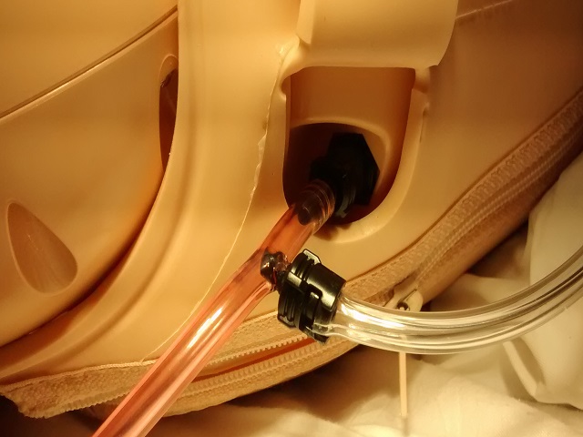
- Unzip the skin on the left side of the manikin and run the wound care tubing underneath, exiting the skin through the opening made for the defibrillator connection. Allow the opposite end to exit the skin around the arm at the shoulder where it can be connected to the left shoulder bleeding port.
- Place JP drain with tubing connected underneath the distal end of the chest plate along-side manikins left chest rise bladder with tubing pointed towards the left side of the chest.
- Zip up the left side of the manikin leaving the tubing exposed only where it connects to the bleeding port and where it exits the manikin as the "chest tube".
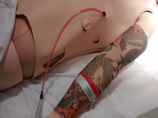
- Prepare chest drainage collection system per manufacturer instructions. Connect and secure the "chest tube" to the chest drainage collection system. Apply dressing as desired to the chest tube site.
- Turn on the SimMan3G manikin and fill with simulated blood. Once filled with blood you can utilize the controls within the software to control the flow of bleeding. Allow as much drainage into the system as you desire. As the manikin breathes the JP drain should act as a bellows, changing the air pressure in the system just enough to provide for tidaling in the water seal chamber and in the drainage tubing.
- Attach to suction and adjust the level of suction as desired or leave to water seal. Any bubbling in the water seal chamber will provide an opportunity to discuss the detection and correction of air leaks in the collection system and/or the resolution of pneumothorax after chest tube placement.
Images


Video
HomeGrown Disclaimer
The information contained within this website is for information purposes only. While the website is monitored in an attempt to keep the information up to date and accurate, be aware that there are no representations or warranties of any kind, express or implied, about the completeness, accuracy, reliability, and/or suitability being made. The sponsors of this website are not liable for any loss or damage that may result from using information contained within this website. Any reliance you place on the information contained within this website is strictly at your own risk.
Please note that sections of this website include postings of individuals not associated with the website sponsors. These postings are not endorsed or warrantied by the website, and use of such information is at your own risk.
Always check the user guide/manuals provided by the manufacturer of your manikin or task trainer. Using products that are not sanctioned may invalidate the product warranty. (For example: Some products could stain the skin on a manikin. Liquids used around electrical parts may cause malfunctions.)